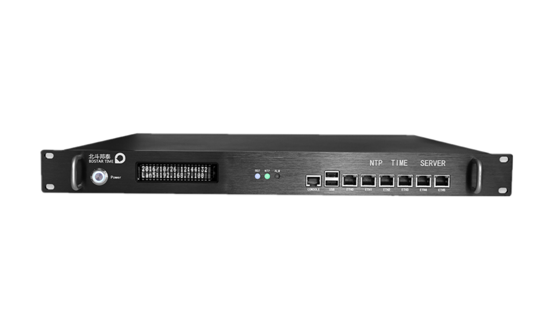
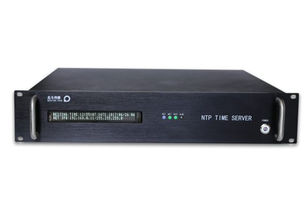
home >> High precision time-frequency >> T900-P Fiber optic high-precision time transfer systemFiber optic time tra

Product Description:
The T900-P Fiber High-Precision Time Transmission Equipment is a high-precision timing system based on wavelength division multiplexing (WDM) technology. The system consists of a Central Station and Terminal Stations. The Central Station comprises the Time-Frequency Interface Unit, Time-Frequency Measurement Unit, Time-Frequency Signal Packaging Unit, Electro-Optical and Opto-Electrical Conversion Unit, and Wavelength Multiplexing/De-multiplexing Unit.
The Terminal Station consists of the Wavelength Multiplexing/De-multiplexing Unit, Electro-Optical and Opto-Electrical Conversion Unit, and Time-Frequency Measurement Servo Unit. This timing system utilizes the classic bidirectional time comparison method, leveraging the fiber optic channel (DWDM wavelength channels) to achieve high-precision time-frequency synchronization. The equipment offers stable operation, strong interference resistance, and can achieve a synchronization accuracy of 40ps over a distance of 100 kilometers. It is suitable for applications in fields with high requirements for synchronization accuracy, such as deep space exploration, defense, and scientific research.
Technical Specifications: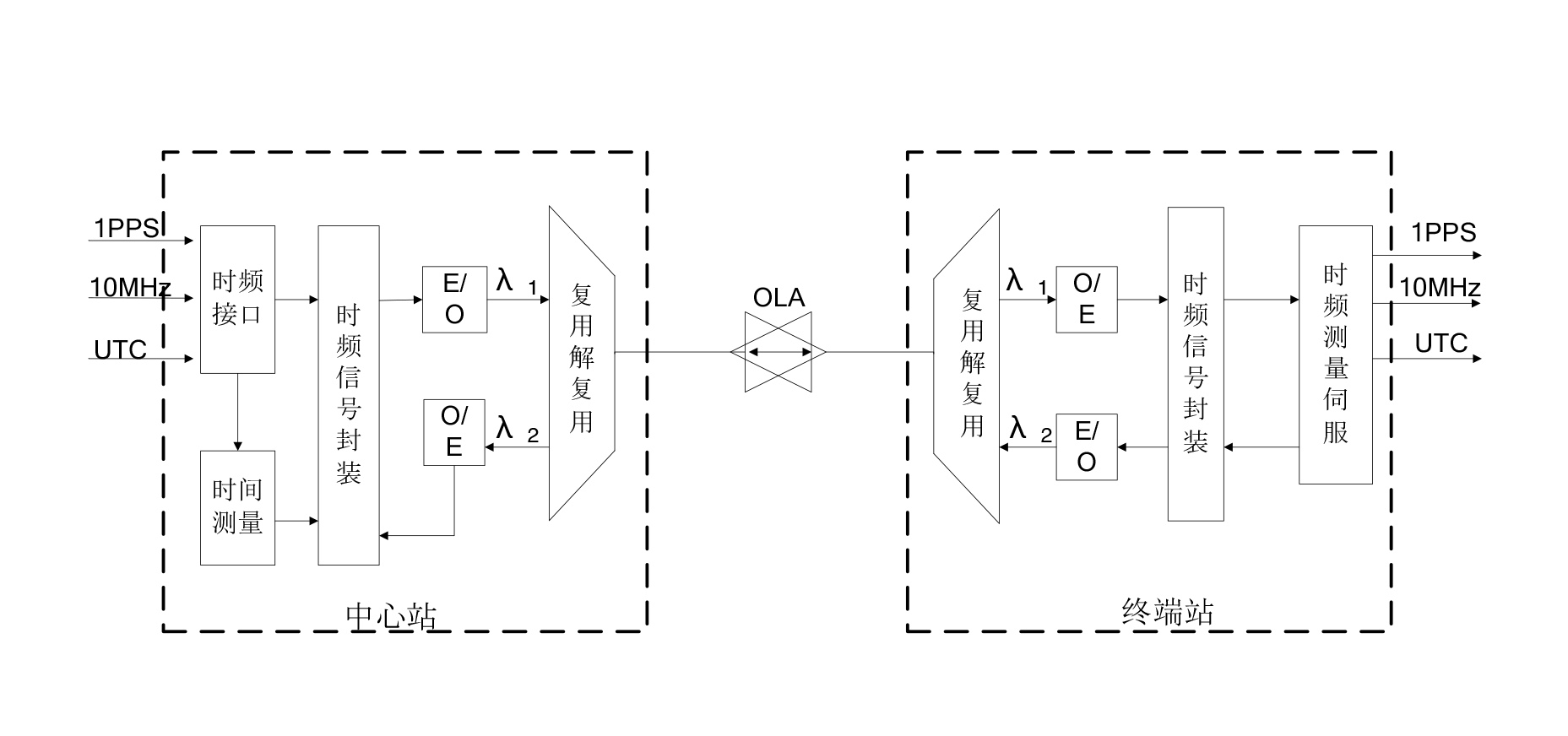 Central Station:
The Central Station is primarily composed of the Electro-Optical Module, High-Precision Measurement Module, Time-Frequency Interface, and Optical Filtering Processing Module.
Electro-Optical Module:
The electro-optical system module used for bidirectional time comparison performs two main functions: first, it combines the local atomic clock's second pulse, 10MHz/100MHz clock, and a small amount of data information into a continuous bitstream and sends it to the remote end using DWDM optical modules. Second, it converts the received optical signal bitstream through electro-optical conversion, extracting the required second pulse, and sends it to the Time Interval Measurement Module for time comparison with the local second pulse. The onboard microcontroller is used to report the measurement results. The design focuses on optical-electrical delay control and circuit signal noise jitter suppression.
Measurement Module:
The Time Measurement Module performs time interval measurement, temperature measurement, and communication with the PC. The time and temperature measurements are carried out by the FPGA in collaboration with the measurement chip. The measured data is processed by the FPGA and sent to the PC via a serial port for time comparison and clock discipline. The product utilizes time interpolation technology based on mature measurement chips and subsequent filtering algorithms to ensure measurement resolution and accuracy. Tested jitter introduced by the time measurement module is less than 200ps peak-to-peak and less than 30ps root mean square, with insensitivity to temperature. The main factor affecting measurement performance is fast-variant random noise, which can be filtered, resulting in even smaller jitter, fully meeting the equipment's requirements.
Ring Resonator and Filter:
The proposed solution uses a ring resonator and filter to isolate bidirectional wavelengths in a single optical fiber. The ring resonator achieves high isolation with less than 0.8dB insertion loss. The filter has a 3dB bandwidth of 0.2nm and insertion loss less than 1dB.
Time-Frequency Interface:
The Central Station requires one channel of second pulse signal and one channel of 10MHz/100MHz frequency signal, with two additional SMA interfaces reserved for backup purposes.
Power and Power Consumption:
The Central Station is powered by AC 220V with a peak-to-peak voltage fluctuation of less than 20% and a power consumption of approximately 40W.
Structural Design:
The equipment's Central Station chassis is a standard 19-inch rack mount with a height of 2U (440×89×350mm) and a depth of 350mm.
Central Terminal Station:
The Terminal Station consists of the Electro-Optical Module, High-Precision Measurement Module, Time-Frequency Servo Regeneration Module, Time
-Frequency Interface, and Optical Filtering Processing Module.
Time-Frequency Servo Regeneration Module:
The high-precision time servo module operates by measuring the time difference between the second pulse received by the Terminal Station in the fiber time transmission system and the locally controlled oscillator's generated second pulse. It processes this time difference with the corresponding algorithm, suppressing measurement errors introduced by noise and disturbances, thus obtaining the true clock difference between the time-frequency center and the Terminal Station. The clock difference is then used to control the Terminal Station's high-stability voltage-controlled oscillator using a specific algorithm to generate seconds pulse and frequency signals that are highly synchronized and stable with the time-frequency center. The time servo system can overcome the random errors introduced by the second pulse during fiber optic channel transmission, ensuring the fiber timing system's short-term and long-term high precision and stability. It can also use the Terminal Station's high-stability clock to provide the Terminal Station with timekeeping functions over a certain period.
|
Key Features:
● Synchronization accuracy of up to 40ps over a distance of 100km.
● Selectable working wavelengths.
● Customizable to support longer distances.
● Industrial-grade design with a compact structure.
● Unique interference monitoring and mitigation technology.
● Support for UTC information transmission.
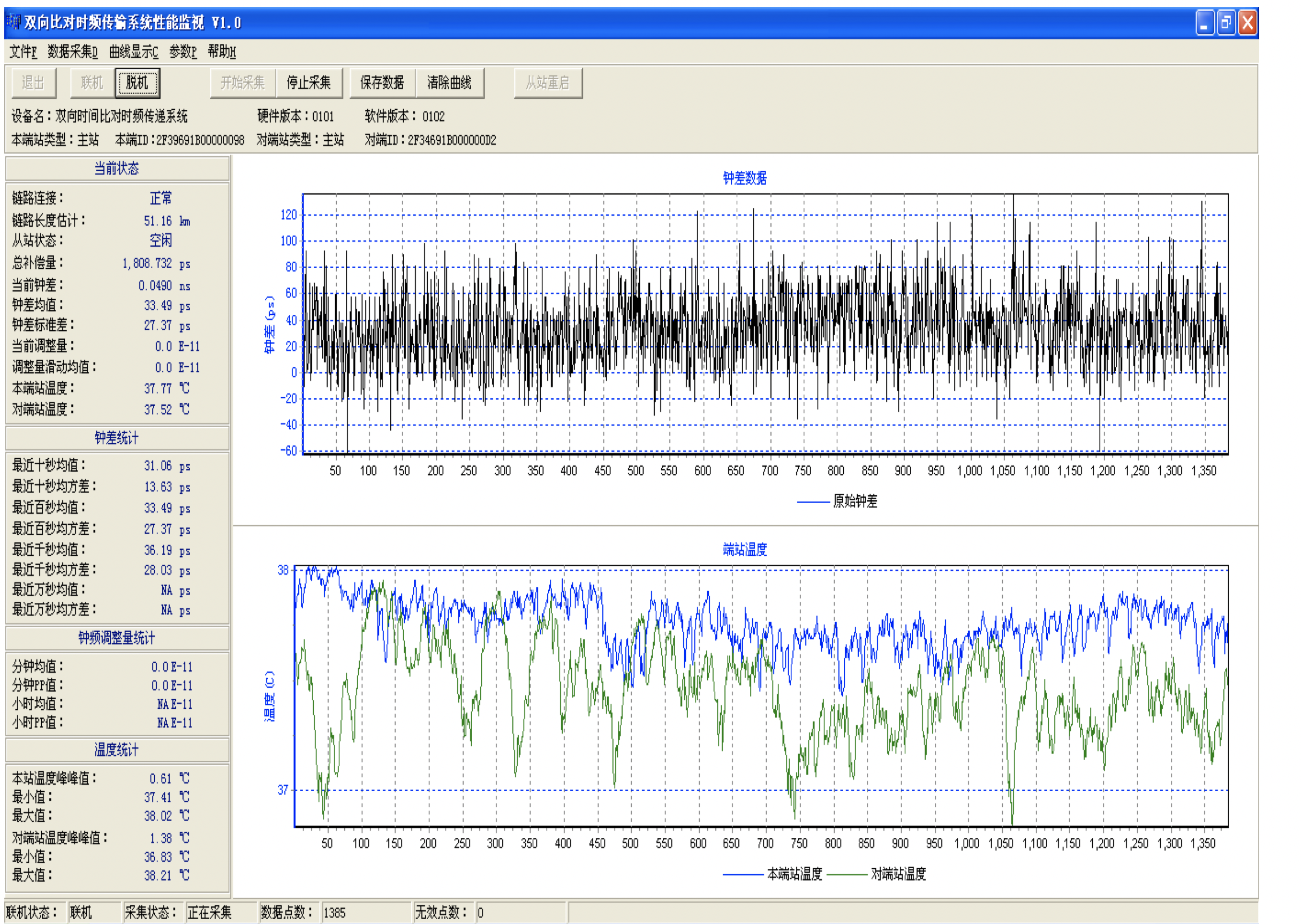
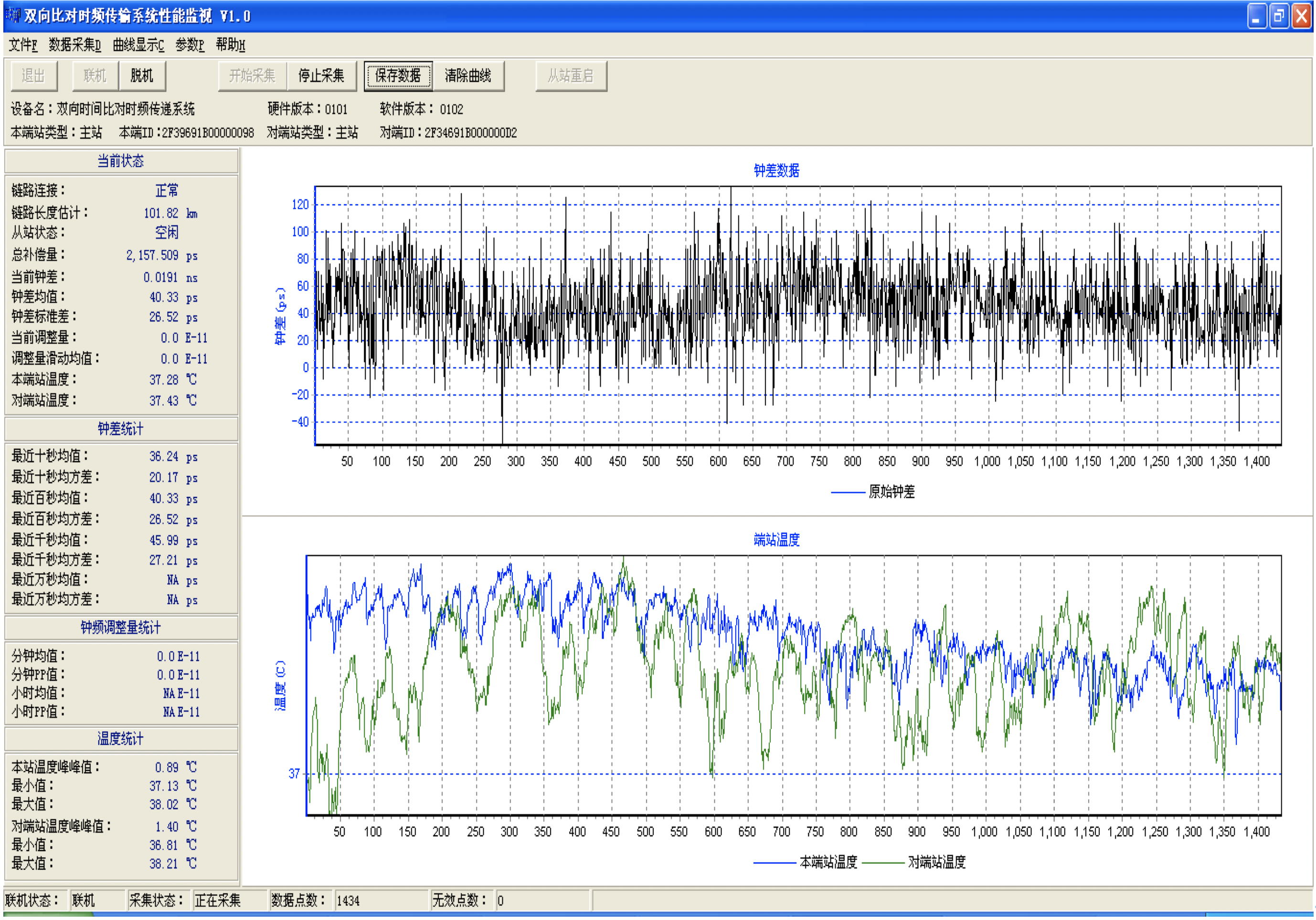
During operation, the equipment utilizes PC software running the time servo function to monitor and analyze the real-time clock source difference measured at both ends of the system. Based on relevant principles, the software continuously adjusts and controls the servo clock. The equipment's time servo software interface is shown in the figure below:
 Time-Frequency Interface:
The terminal station has one channel of second pulse signal and one channel of frequency signal for terminal comparison of time-frequency signals, both using SMA interfaces. The terminal station outputs one channel of second pulse signal and one channel of frequency signal, also through SMA interfaces.
Power Supply and Power Consumption:
The timing center station is powered by AC 220V with a peak-to-peak voltage fluctuation of less than 20%, and the power consumption is approximately 50W.
Structural Design:
The timing terminal station's rear panel has output interfaces consisting of one channel of frequency signal and one channel of second signal, both using SMA interfaces. Additionally, one channel of frequency signal and one channel of second signal are used as inputs for time-frequency comparison, utilizing SMA interfaces. The rest of the structural design is the same as the timing center station.
Performance Testing:
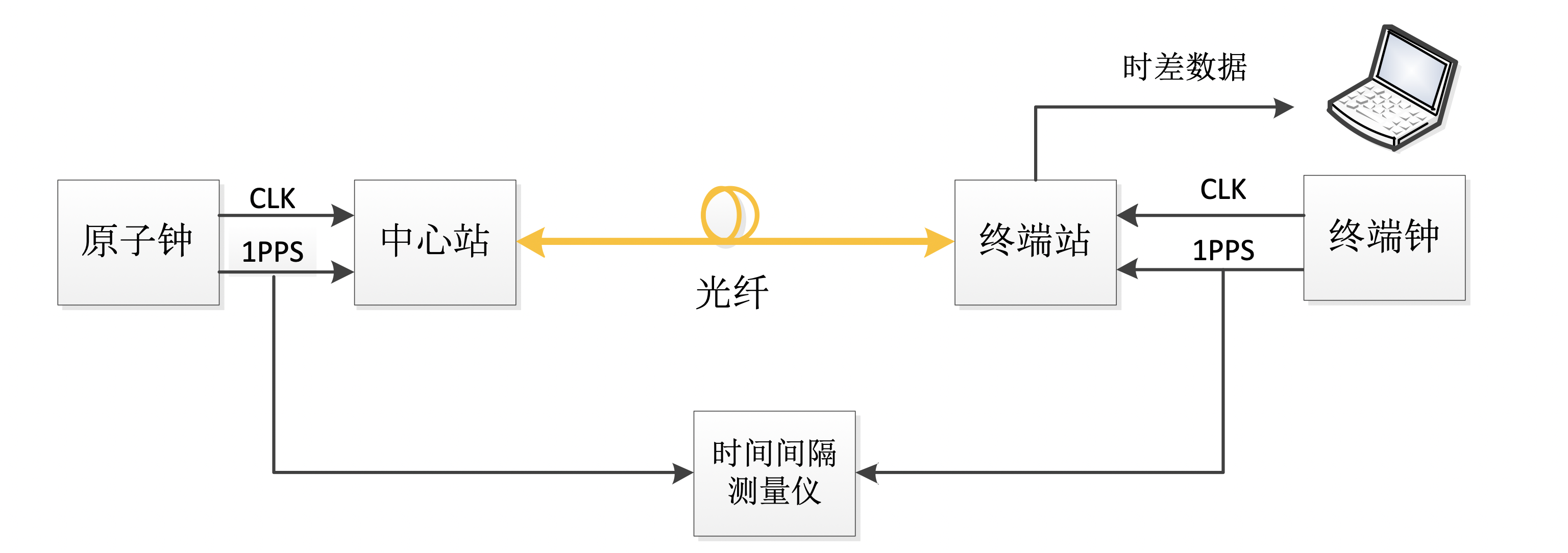
Testing Connection Diagram
Measurement Results of SR620 and Comparison Device over a 100km Optical Fiber
SR620 Measurement Results:
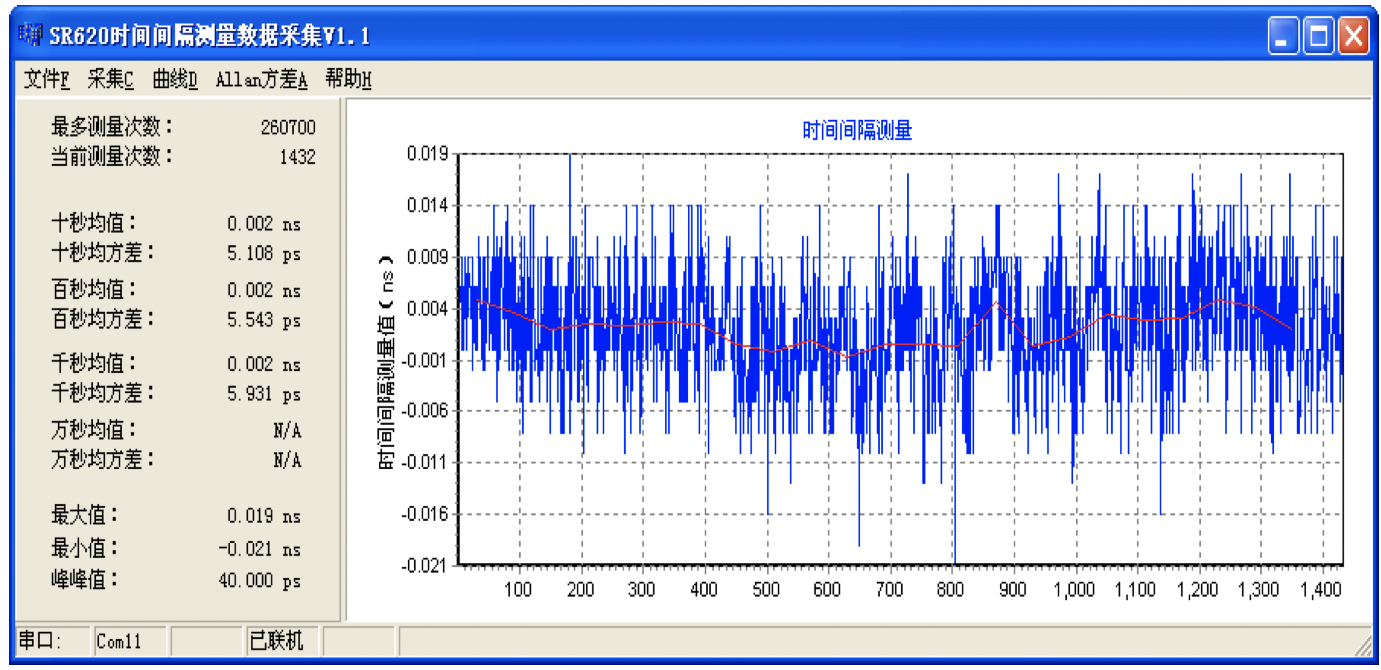
Comparison System Measurement Results:
 |
Documentation
T900-P Fiber optic high-precision time transfer system【PDF】data
PDF

