home >> High precision time-frequency >> T900-F Fiber optic high-precision frequency transmission sysHigh-precision frequ

Product Description:
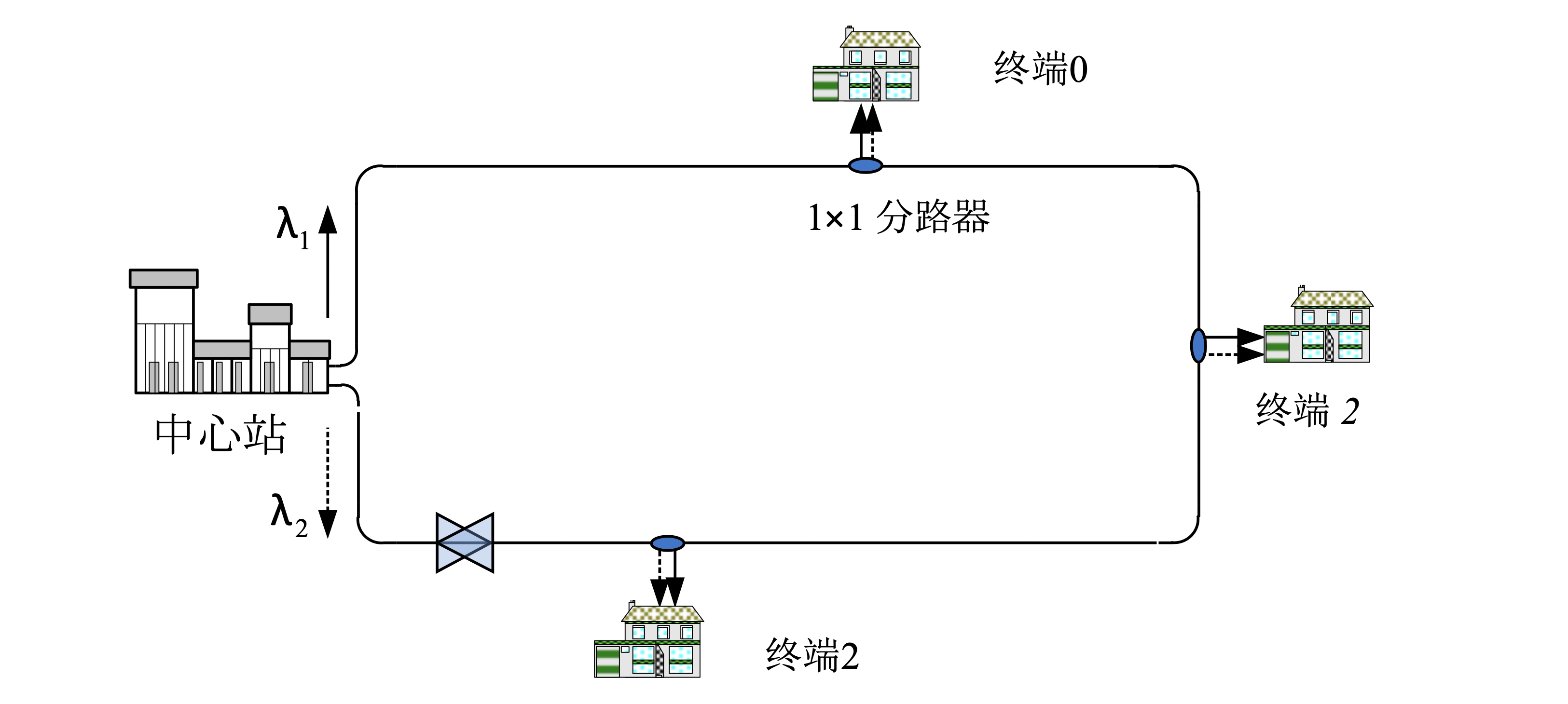
The T900-F Fiber High-Precision Frequency Transmission Device is a GPS/Beidou synchronized clock system based on a ring network multi-point high-precision frequency transmission technology. The system consists of two main parts: the central station and the terminal station. The frequency transmission central station is primarily composed of optoelectronic units, high-precision measurement compensation units, time-frequency interface units, and ring filter optical processing units.
The frequency transmission terminal station is mainly composed of optoelectronic units, high-precision measurement compensation units, time-frequency interface units, and optical filter processing units. In this system, the central station only needs to send frequency signals in a closed-loop and compensate for the phase fluctuations of the entire link. There is no need for phase stabilization design for individual nodes. Whether adding or reducing users within the network, the system's scalability can be significantly improved by simply adjusting the optical power, thereby reducing maintenance complexity.
The reproduced frequency is a 100MHz signal with relative frequency stability of 3×10^-14@1S and 1×10^-16@10000S. It can be applied in various fields such as fundamental science, deep space exploration, and modern high-tech equipment.
Key Features:
● Reproducibility with stability of 1×10^-16 over 50km and 1×10^-16 for ten thousand seconds.
● Selectable working wavelength.
● Customizable to support longer distances.
● Industrial-grade design with a compact structure.
● Unique interference monitoring and mitigation technology.
● Convenient ring structure for easy expansion.
Technical Specifications: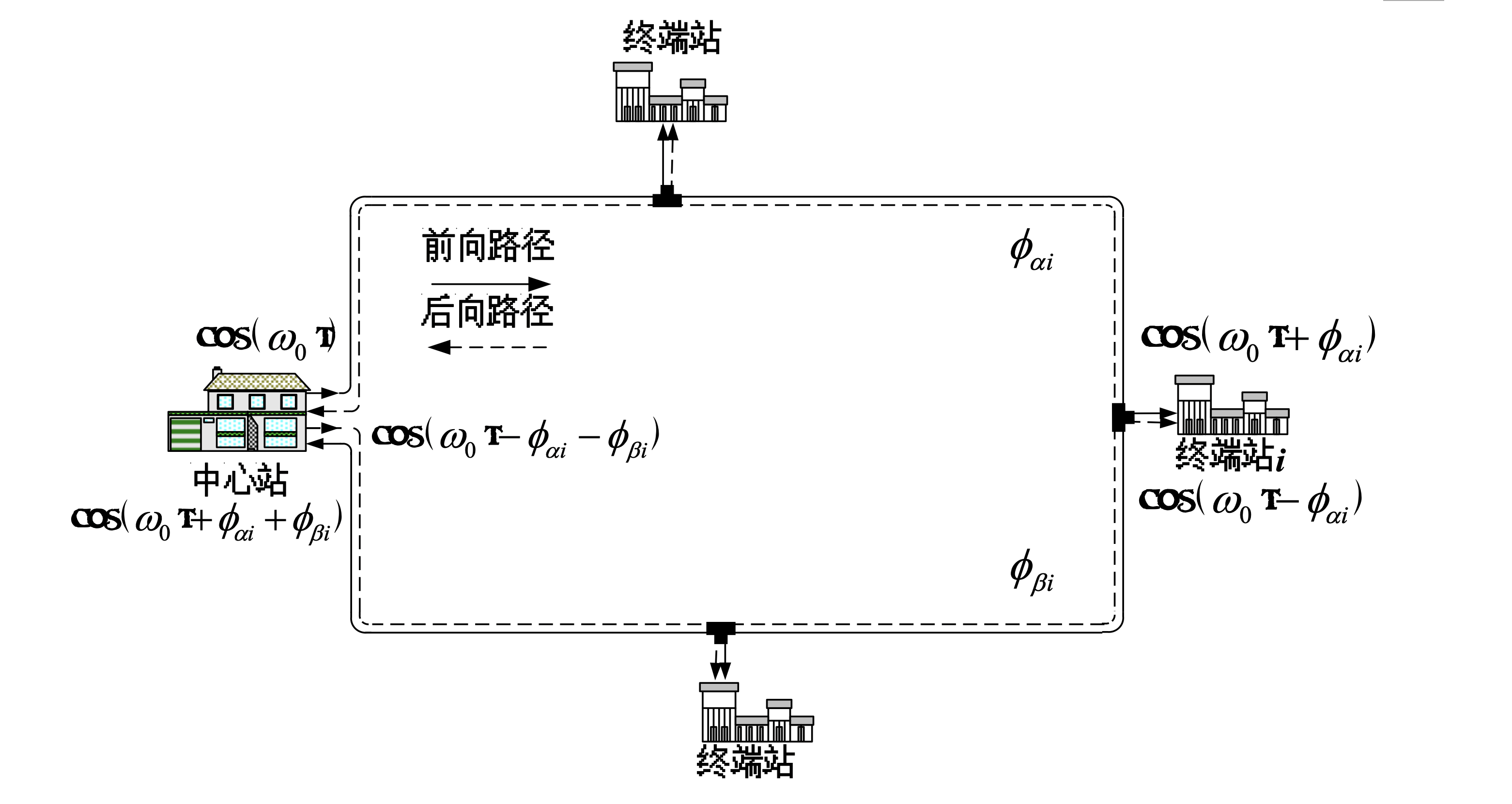 Performance Testing:
To assess performance, a 50km multi-point transmission experimental system is set up as shown in the diagram, with some fiber spools placed inside temperature-controlled boxes to simulate link temperature variations. The 1GHz frequency input from the central station and the compensated 1GHz frequency recovered from the terminal station are downconverted to 100MHz and sent to the Microsemi 5125A frequency stability and additional phase noise measurement instrument. The test results of the 5th downconversion to 200MHz intermediate frequency signal are shown in the graph.
- Transmission Distance: 50km
- Frequency Stability Loss: 3×10^-14@1S, 6×10^-14@10S, 2×10^-15@100S, 6×10^-16@1000S, 1×10^-16@10000S
- Additional Phase Noise: -110dBc/Hz @ 10Hz
|
Important Functions:
In the process of frequency signal distribution, the central station of this system only needs to send frequency signals in a closed-loop and compensate for the phase fluctuations of the entire link. There is no need for phase stabilization design for individual nodes. Whether adding or reducing users within the network, apart from controlling the received optical power to some extent, the central station requires minimal adjustments. This greatly enhances the system's scalability and reduces maintenance complexity. Additionally, any terminal station at any node position on the ring can implement stable phase reception in the same manner, allowing new users to conveniently join the link at any nearby node.
 Central Station:
The central station primarily consists of optoelectronic units, high-precision measurement compensation units, time-frequency interfaces, and ring filter optical processing units.
Optoelectronic Module:
The optoelectronic module serves three main functions: first, modulating the local 1GHz frequency signal onto a specific optical wavelength for forward signal transmission; second, receiving the forward optical signal transmitted by the ring network and converting it into an electrical signal for precise measurement by the compensation module; and third, modulating the compensated 1GHz frequency signal onto another specific optical wavelength for reverse signal transmission. The optoelectronic module design emphasizes linear modulation, wavelength, and power stability, with the laser module utilizing temperature-controlled DFB direct modulation lasers to avoid polarization mode dispersion. The modulated signal light passes through a polarization scrambler to mitigate its impact on system performance. The optoelectronic detector is a low-noise PIN+TIA receiving component.
Measurement Compensation Module:
The measurement compensation module utilizes a heterodyne phase-locking mechanism to accurately measure the phase fluctuations of the entire ring and implements precise compensation through either active or passive mechanisms. It achieves a measurement compensation accuracy of the order of 0.01ps.
Ring Filter:
Ring resonators and filters are employed to separate bi-directional wavelengths in a single fiber. The ring filter is designed to have high isolation and low insertion loss, with isolation reaching 30dB and insertion loss less than 0.8dB. The filter's 3dB bandwidth is 0.2nm, and its insertion loss is less than 1dB.
Frequency Input Interface:
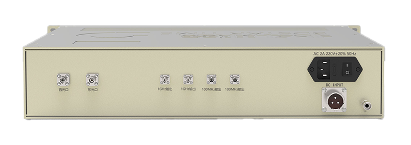
The central station requires one 1GHz signal and one 100MHz downconverted measurement frequency signal as inputs, with an input power greater than 7dBm and using SMA connectors. Two additional SMA connectors are reserved for backup purposes.
Power and Consumption:
The central station is powered by AC 220V with fluctuations less than 20%, and the power consumption is approximately 100W.
Structural Design:
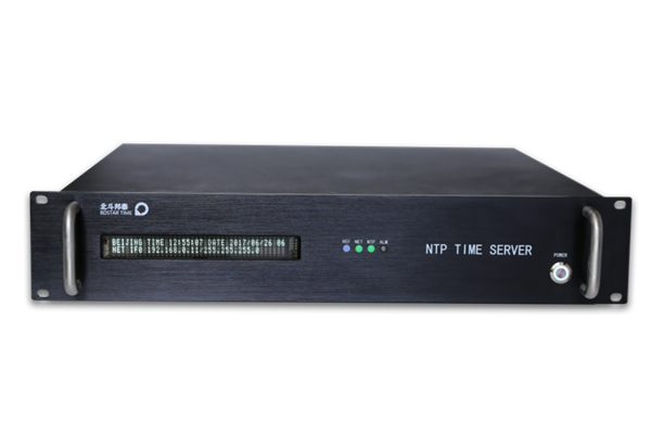
The central station equipment is designed with a standard 19-inch rack mount size and a height of 2U (440×89×400mm).
Terminal Station:
The terminal station mainly consists of optoelectronic modules, high-precision measurement compensation modules, time-frequency interfaces, and optical filter processing modules.
Optical Splitting and Filtering:
Within the ring network, optical splitters and filters are used to extract forward and reverse signals. The additional loss of the splitter is less than 0.5dB. The filter's 3dB bandwidth is 0.2nm, and its insertion loss is less than 1dB.
Frequency Output Interface:
The terminal station provides two frequency signal outputs with SMA connectors, and the output power is greater than 10dBm. There are also two additional SMA output connectors reserved for backup purposes.
Power and Consumption:
The terminal station is powered by AC 220V with fluctuations less than 20%, and the power consumption is approximately 40W.
Structural Design:
The terminal station equipment is designed with a standard 19-inch rack mount size and a height of 2U (440×89×400mm).
|
Documentation
T900-F Fiber optic high-precision frequency transmission sys【PDF】data
PDF

