home >> Measurement and testing instru >> CNT-90 Frequency counter/analyzertime interval measur

Product Description
The CNT-90 Counter/Time Interval Analyzer is an excellent tool with outstanding performance for measurement, analysis, and calibration processes. The CNT-90 can measure frequency, time intervals, and phase. When communicating with the internal 750k data memory, the measurement speed can reach up to 250,000 measurements per second, making it a high-performance frequency counter. The CNT-90 is affordable and easy to use, providing graphical display capabilities and convenient control over measurements.
World-Class Performance
Compared to other brand frequency counters on the market, the CNT-90 Counter/Time Interval Analyzer offers the following world-leading performance features:
● Fast measurement speed: In block mode, the measurement result transfer speed via GPIB/USB interface reaches up to 5,000 measurements per second. This high transfer speed significantly improves the throughput of user testing systems, saving up to 90% of testing time and reducing costs.
● High resolution: High resolution is essential for production testing and research and development. The CNT-90 meets this requirement with its 100 ps single-shot time resolution and 12 digits/second frequency measurement resolution. The measurement results can be displayed with up to 14 digits.
● Modulation domain analysis: By communicating with the internal 750k memory at a measurement rate of 250k/s, rapid frequency changes of the measured signal can be captured in real-time. With the optional Time View modulation domain analysis software, the CNT-90 can transform into a high-performance modulation domain analyzer.
● Wide frequency range: The 20 GHz frequency measurement range satisfies the measurement needs of most microwave signals, including continuous wave and short pulse measurements. Users do not need to spend additional money on purchasing a microwave frequency counter.
CNT-90 Technical Specifications:
Measurement Functions
All measurements are displayed with a main parameter value and several small auxiliary parameter values (lower resolution), and some measurements can only be read as auxiliary parameters.
Frequency A, B, C
Range:
Inputs A, B: 0.002 Hz to 400 MHz
Input C (option): Up to 3, 8, 14, or 20 GHz
Resolution: 12 digits, 1 s measurement time (normal mode)
Auxiliary parameters: Vmax, Vmin, Vp-p
Pulse Train Frequency A, B, C (options 10 and 14/14B)
The carrier frequency and pulse repetition frequency (PRF) of a repetitive pulse train signal can be measured in the absence of external control signals and with selectable start delay.
Functions: Frequency in a short pulse train (Hz)
PRF (Hz)
Range: Inputs A, B, C: Refer to frequency technical specifications
Minimum pulse duration in a short pulse train (Channels A and B): 40 ns minimum (80 ns above 160 MHz)
Minimum number of pulses in a short pulse train:
Input A or B: 3 (6 above 160 MHz)
Input C: 3 × predetermined factor
PRF range: 0.5 Hz to 1 MHz
Start delay: 10 ns to 2 s, 10 ns resolution
Auxiliary parameter: PRF
Period A, B, C
Mode: Single-shot mode, averaging mode
Range:
Inputs A, B: 3.3 ns to 1000 s (single-shot, averaging)
Input C (option): 10 ns to 330,125,70, or 50 ps
Resolution: 100 ps (single-shot); 12 digits/second (averaging)
Auxiliary parameters: Vmax, Vmin, Vp-p
Ratio A/B, B/A, C/A, C/B
Range: (10−9) to
10^11
Input frequencies:
Inputs A, B: 0.1 Hz to 200 MHz
Input C (option): Up to 3, 8, 14, or 20 GHz
Auxiliary parameters: Frequency 1 and Frequency 2
Time Interval A-B, B-A, A-A, B-B
Range:
Normal calculation: 0 ns to +106 s
Clever calculation: -106 s to +106 s
Resolution: 100 ps (single-shot)
Minimum pulse width: 1.6 ns
Frequency range: Up to 160 MHz
Clever calculation: Used to determine the sign of clever time interval measurements (A before B or A after B)
Positive Pulse Width and Negative Pulse Width A, B
Range: 2.3 ns to 106 s
Minimum pulse width: 2.3 ns
Auxiliary parameters: Vmax, Vmin, Vp-p
Rise and Fall Times A, B
Range: 1.5 ns to 106 s
Trigger level: 10% and 90% of signal amplitude
Minimum pulse width: 1.6 ns
Auxiliary parameters: Transition time, Vmax, Vmin
Positive Duty Cycle and Negative Duty Cycle A, B
Range: 0.000001 to 0.999999
Frequency range: 0.1 Hz to 400 MHz
Auxiliary parameters: Period, pulse width
Phase of A relative to B, Phase of B relative to A
Range: -180 degrees to +360 degrees
Resolution: Single-period: 0.001 degrees below 10 kHz, decreasing to 1 degree above 10 MHz. Resolution can be improved through averaging (statistical method).
Frequency range: Up to 160 MHz
Auxiliary parameters: Frequency A, Va/Vb (dB)
Vmax, Vmin, Vp-p A, B
Range: -50 V to +50 V, -5 V to +5 V
The range is limited by the maximum safe input voltage technical specifications. (See input A, B technical specifications)
Frequency range: DC, 1 Hz to 400 MHz
Mode: Vmax, Vmin, Vp-p
Resolution: 3 mV
Uncertainty (5 V range, standard conditions):
DC, 1 Hz to 1 kHz: 1% + 15 mV
1 kHz to 20 MHz: 3% + 15 mV
20 MHz to 100 MHz: 10% + 15 mV
100 MHz to 400 MHz: 30% + 15 mV
Auxiliary parameters: Vmax, Vmin, Vp-p
Time Tag A, B, C
The raw time tag data on inputs A or B, along with pulse count, can be accessed via GPIB or USB.
Maximum sampling rate: See GPIB technical specifications
Maximum frequency: 160 MHz
Time tag resolution: 100 ps
Input and Output Technical Specifications
Inputs A and B
Frequency range:
DC coupling: DC to 400 MHz
AC coupling: 10 Hz to 400 MHz
Impedance: 1 MΩ // 20 pF or 50Ω (VSWR ≤ 2:1)
Trigger edge: Positive or negative
Maximum channel timing difference: 500 ps
Sensitivity:
DC to 200 MHz: 15 mVrms
200 to 400 MHz: 25 mVrms
Attenuation: ×1, ×10
Dynamic range (×1): 30 mVp-p to 10 Vp-p within ±5 V window
Trigger level: Readout on the display
Resolution: 3 mV
Uncertainty (×1): ±(15 mV + 1% of trigger level)
Auto trigger level: Automatically set to 50% of input signal amplitude (set at 10% and 90% of input signal amplitude for rise/fall time measurements)
Auto hysteresis:
Time: Minimum hysteresis window (hysteresis compensation)
Frequency: 1/3 of input signal amplitude
Analog anti-aliasing filter: Rated at 100 kHz, RC type
Digital low-pass filter: 1 Hz to 50 MHz cutoff frequency
Maximum safe voltage:
1 MΩ: 350 V (DC+ACpk) at 440 Hz, decreasing to 12 Vrms at 1 MHz (×1)
50Ω: 12 Vrms
Connector: BNC
Input C (Option 10)
Operating input voltage range:
100 to 300 MHz: 20 mVrms to 12 Vrms
0.3 to 2.5 GHz: 10 mVrms to 12 Vrms
2.5 to 2.7 GHz: 20 mVrms to 12 Vrms
2.7 to 3.0 GHz: 40 mVrms to 12 Vrms
Predetermined factor: 16
Impedance: 50Ω nominal, VSWR < 2.5:1
Maximum safe voltage: 12 Vrms, pin diode protected
Connector: N-type (female)
Input C (Option 13)
Operating input voltage range:
200 to 300 MHz: 40 mVrms to 7 Vrms (typical)
300 to 500 MHz: 20 mVrms to 7 Vrms
0.5 to 3.0 GHz: 10 mVrms to 7 Vrms
3.0 to 4.5 GHz: 20 mVrms to 7 Vrms
4.5 to 6.0 GHz: 40 mVrms to 7 Vrms
6.0 to 8 GHz: 80 mVrms to 7 Vrms
Predetermined factor: 256
Impedance: 50Ω nominal, VSWR < 2.5:1
Maximum safe voltage: 7 Vrms
Connector: N-type (female)
Input C (Options 14 and 14B)
Frequency range: 0.2 to 14 GHz (Option 14)
0.25 to 20 GHz (Option 14B)
Operating input voltage range:
250 to 500 MHz:
-21 to +27 dBm
0.5 to 14 GHz: -27 to +27 dBm
14 to 18 GHz: -27 to +27 dBm (for Option 14B only)
18 to 20 GHz: -21 to +27 dBm (for Option 14B only)
Predetermined factor: 128
Impedance: 50Ω nominal, VSWR < 2.0:1
Modulation tolerance: >90% within sensitivity range
Maximum safe voltage: +27 dBm
Connector: Precision N-type (female)
Rear Panel Inputs and Outputs
Reference input: 1, 5, or 10 MHz, 0.1 to 5 Vrms sine wave, impedance ≥ 1 kΩ
Reference output: 10 MHz, >1 Vrms sine wave into 50Ω
Holdoff input: All measurement functions on hold
Impedance: Approximately 1 kΩ
Frequency range: DC to 80 MHz
Rear panel measurement inputs: A, B, C (Options 11/90)
Impedance: 1 MΩ // 50 pF or 50Ω (VSWR ≤ 2:1)
Connectors: SMA type for rear panel input C, BNC for all other inputs/outputs
Auxiliary Functions
Trigger inhibit
Delay range: 20 ns to 2 s, 10 ns resolution
External start-stop holdoff
Mode: Start, stop, start-stop holdoff
Input channels: A, B, or E-rear panel
Maximum repetition rate for holdoff signal:
Channels A, B: 160 MHz
Channel E: 80 MHz
Start delay range: 20 ns to 2 s, 10 ns resolution
Statistical processing
Functions: Maximum, minimum, average, Δmax-Min, standard deviation, Allan deviation
Display: Numeric, histogram, or trend chart
Sample size: 2 to 2 × 10^9 samples
Limiting criteria: OFF cutoff or capture data above limit/below limit/within limit or outside limit range.
Measurement step: Step time range: 4 µs to 500 s
Mathematical processing
Functions: (K * X + L) / M and (K / X + L) / M. X is the current reading, while K, L, and M are constants set via the keyboard or using fixed reference values (0 X).
Other Functions
Measurement time: 20 ns to 1000 s for frequency, pulse train, and period average functions. For other measurement functions, the measurement time is one period.
Timebase reference: Internal, external, or automatic
Display hold: Freezing the result until Restart initiates a new measurement round.
Limit alarms: Graphical display on the front panel and/or SRQ message via GPIB.
Limits: Lower limit, upper limit
Setting: OFF cutoff or alarm if data is above limit/below limit/within limit range or outside limit range.
Alarm state: STOP or CONTINUE
Display: Numeric + Graphical
Stored instrument setups: 20
Instrument setups can be saved and recalled using the internal non-volatile memory. Ten of them can be protected by the user.
Display: Backlit LCD graphical screen for menu control, numeric readout, and status information display.
Digits: 14-digit display in numeric mode.
Resolution: 320 * 97 pixels
|
Affordable and High-Performance Counter/Analyzer
- The instrument has a high transfer speed of up to 250k measurements/second between the instrument and the internal data memory of 750k.
- Extremely fast GPIB/USB bus transfer speed: 500 measurements/second (single measurement mode); 5k measurements/second (group measurement mode).
- High measurement resolution: 12 digits/second (frequency), 100 ps (time), 0.001° (phase).
- Measurement results can be displayed with up to 14 digits.
- Frequency range: Standard configuration is 400 MHz, and high-frequency channels can reach 3, 8, 14, and 20 GHz with options.
- User-friendly: Multi-parameter display of measurement results and graphical display functions, including statistics, histograms, and trend charts.
- Excellent cost-performance ratio.
- The performance of the CNT-90 Time Interval Counter/Frequency Counter/Analyzer surpasses any other frequency counter on the market, except for the CNT-91 frequency counter introduced by Pendulum.
- Graphical display: The instrument provides graphical display functions for measurement results, including histograms, trend charts, numeric statistics, and modulation domain analysis. These graphical display functions help users better understand the distribution of random signals and the variation of measured signal parameters over time, from slow drift to fast jitter and modulation.
- Standardized GPIB and USB interfaces: Standardized interface settings eliminate the need for installing a GPIB interface on a PC. The GPIB interface operates in two different modes: SCPI/GPIB and 53131A emulation mode, allowing easy replacement of frequency counters from other brands in existing Automatic Test Equipment (ATE) systems. This plug-and-play feature greatly reduces the need for reprogramming the existing system commands.
- Wide frequency measurement range: With options, the frequency measurement range of the CNT-90 Time Interval Counter/Frequency Counter/Analyzer can reach up to 20 GHz. Users can use the CNT-90 series to measure the frequency of continuous microwave signals as well as short pulse train signals, with a minimum pulse duration of 40 ns.
- Menu-driven setup: Menu-driven setup reduces the risk of errors. The multi-parameter display of measurement results provides valuable signal information, reducing the need for additional instruments such as digital voltmeters (DVMs) and oscilloscopes.
Versatile Functions and Advanced Technology
The CNT-90 Time Interval Counter/Frequency Counter/Analyzer not only offers world-class performance but also serves as the optimal tool for various specialized measurements. The CNT-90 has the following features:
- Zero dead-time measurement technology and continuous time tagging of trigger events: The availability of zero dead-time measurement and continuous time tagging of trigger events enables the measurement results to be used for calculating Allan deviation. These features are particularly valuable in specific measurements in mechanical fields (e.g., rotary encoder testing) and medical fields (e.g., neural impulses/respiration cycles) where every cycle of the measured object needs to be captured.
- Limiting criteria: Limiting criteria are convenient tools for correctly calculating statistical parameters. Digital pulses in discrete clusters (e.g., CD players and HDB3-encoded data) often exhibit jitter. By using limiting criteria, users can verify the jitter by separating individual discrete clusters in the calculations.
- Hysteresis compensation: In time interval measurements, hysteresis compensation significantly reduces trigger level errors. Most frequency counters on the market currently have trigger level errors of 15-20 mV, while the CNT-90 with hysteresis compensation has a typical trigger level error of only 2.5 mV. This means that the trigger accuracy is improved by 6-8 times in critical time interval measurements.
- Battery option
The CNT-
90 Time Interval Counter/Frequency Counter/Analyzer offers a battery option, model 23/90, with a capacity of 90Wh. In measurement environments without AC power, the battery option can provide power to the instrument for at least 4.5 hours.
In standby mode, the battery can sustain continuous operation of the OCXO (oven-controlled crystal oscillator) for up to 24 hours. The battery option of the frequency counter/analyzer has valuable applications in the following scenarios:
- Measurements in environments without access to AC power.
- Continuous power supply to maintain the stability of the OCXO during transportation. After transporting the instrument to the measurement site, it can be used immediately without requiring a warm-up period.
- The battery pack functions similarly to a built-in uninterruptible power supply (UPS).
Excellent Graphical Display Features
One of the unique features of the CNT-90 is its graphical display and menu-driven setup. Non-experts can easily perform correct setups without the risk of significant errors.
The instrument employs a multi-parameter display mode, which simultaneously displays additional auxiliary measurement values below the main measurement value on the screen. For example, while displaying the measured frequency value, it also shows auxiliary parameters such as Vmax/Vmin/Vp-p. Similarly, when displaying the measured phase value, it shows auxiliary parameters such as frequency and attenuation. This simultaneous display of multiple parameters eliminates the need for additional test instruments and provides direct answers to common questions, such as "What is the attenuation and phase shift of this filter?"
Measurement results can be displayed numerically or graphically. Graphical displays (histograms, trend charts) provide a deeper understanding of jitter characteristics. The graphical display also offers a better visualization of the measured object's variation over time, from slow drift to rapid modulation (trend chart). Statistical results of the same dataset can be displayed in three different ways: numeric display, histogram display, and trend chart display. It is easy to capture and switch between these three different display modes for the same dataset.
Option 23/90 Battery Unit
Battery Type: Lithium-ion, 90Wh
External DC Input: 10 ~ 18V DC; max 6A
Operating Temperature Range: -20 ~ +40°C
Storage Temperature:
-20 ~ +60°C for one month
-20 ~ +45°C for three months
-20 ~ +20°C for one year
Battery Operation Time (at 25°C):
- ON: >4.5 hours
- Stand-by: >24 hours
Charging: Automatically starts charging when connected to AC power or external DC power
Battery Status Display: Low battery warning displayed on the screen
Weight: 2.3 kg (5.1 lbs)
General Specifications
Environmental Data:
- Compliance: Meets MIL-PRF-28800F, Class 3 standard
- Operating Temperature: 0°C ~ +50°C
- Storage Temperature: -40°C ~ +71°C
- Humidity: 5% ~ 95% (10°C ~ 30°C), 5% ~ 75% (30°C ~ 40°C), 5% ~ 45% (40°C ~ 50°C)
- Altitude: 4600 meters
- Vibration: Passed random vibration and sinusoidal vibration tests according to MIL-PRF-28800F, Class 3 standard
- Shock: Passed half-sine 30G tests according to MIL-PRF-28800F, bench handling standard
- Transportation drop test: Tested with durable hard cases and low-hardness transport cases according to MIL-PRF-28800F standard
- Reliability: Mean Time Between Failures (MTBF) is 30,000 hours (calculated value)
- Safety: Complies with EN61010-1, Pollution Degree 2, Measurement Category I, CSA C22.2 No1010-1, CE standards
- Electromagnetic Compatibility (EMC): Complies with EN61326 (1997); A1 (1998) standard, improved testing level according to EN50082-2, Group 1, Class B, CE standard
- Power Requirements: Basic model: 90 ~ 265Vrms, 45 ~ 440Hz, <40W
Dimensions and Weight:
- Width × Height × Length: 210 × 90 × 395 mm (8.25 × 3.6 × 15.6 in)
- Weight: Net weight 2.7 kg (5.8 lbs), Shipping weight approximately 3.5 kg (7.5 lbs)
Ordering Information:
- Main Unit: CNT-90 400MHz, 100ps Counter/Time Interval Tester, including standard time base.
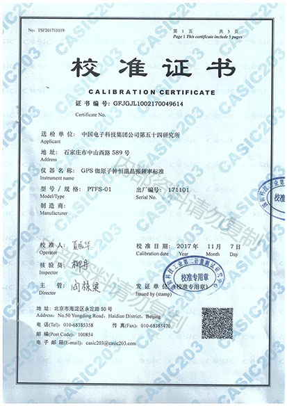
- The instrument includes: 18 months product warranty, power cord, user documentation CD, and calibration certificate.
Input Frequency Options:
- Option 10: 3GHz Input C
- Option 13: 8GHz Input C
- Option 14: 14GHz Input C
- Option 14B: 20GHz Input C
Time Base Options:
- Option 19/90: Mid-stability OCXO; 0.06ppm/month
- Option 30/90: High-stability OCXO; 0.01ppm/month
- Option 40/90: Ultra-high-stability OCXO; 0.003ppm/month
Optional Accessories:
- Option 11/90: Rear Panel Input
- Option 22/90: Rackmount Kit
- Option 23/90: Battery Unit
- Option 27: Soft Transport Case
- Option 27H: Rugged Hard Transport Case
- Option 29/
90: Modulation Domain Analysis Software "Time View" for CNT-90
- Option 90/01: Calibrated Certificate with Standard Oscillator
- Option 90/06: Calibrated Certificate with OCXO
- Option 90/00: Calibrated Certificate with Aging/Week Hold Oscillator
- Option 95/03: Extended 3-year warranty
- Option 95/05: Extended 5-year warranty
- OM-90: English User Manual (Printed Version)
- PM-90: English Programming Manual (Printed Version)
- SM-90: English Service Manual
- GS-90-EN: English Getting Started Guide
- GS-90-FR: French Getting Started Guide
- GS-90-DE: German Getting Started Guide
GPIB Interface:
- Compatibility: IEEE 488.2-1987, SCPI 1999, 53131A compatible mode
- Interface Functions: SH1, AH1, T6, L4, SR1, RL1, DC1, DT1, E2
- Maximum Measurement Rate:
- Through GPIB: 5k readings/second (Block mode)
- 500 readings/second (Individual Get triggered)
- Internal Memory Capacity: CNT-90: up to 750k readings
USB Interface:
- USB Version: 2.0 Full Speed (11Mbit/s)
Measurement:
- Mode: No need for unpacking, menu-controlled
- Frequency Measurements: 0.1, 1, 5, 10, 1.544, and 2.048MHz
|
Documentation
CNT-90 Frequency counter/analyzer【PDF】data
PDF

